
Introduction:
The objective of this project is allowing the Heathkit SB or HW transciever to send the current frequency to a computer, in order to use n1mm or other log programs.
Preliminary considerations.
The current frequency on the HW and SB series radios is calculated by subtracting the LMO and BFO frequencies from the HFO frequency.
I will use a microcontroller to do the counting, math and ci-v processing.
The microcontroller for the first testing is a PIC18F2520. This will present us with some challenges that I plan to overcome either with some logic or a different PIC in the future namely:
- Frequencies being read, this pic will not read more than 1.7 MHz directly, so, I’ll need a divisor.
- Number of external timers, only one is available, so I’ll multiplex the readings. (or use a different pic)
- Input sine wave, must be converted to a square wave to be properly read.
Bellow is a concept of the project.

Measurements:
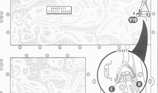
To pick up the signals I’ll follow the instructions on the SB-650 user and assembly guide.
BFO:
The BFO signal is picked at the IF board placing a 220pF cap on point A of the picture.

The signal at this point in the radio, before the 220pF cap has 5.12 Vpp with a bias of around 2V, this will be removed by the cap.

After the said cap the signal has 4.84Vpp with almost no bias.

This signal will be enough for the circuit, but I’ll place some kind of protection before feeding it into the logic circuits.
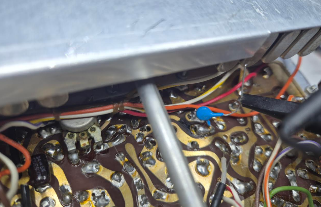
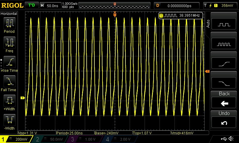
HFO:
This signal is picked up in the band pass circuit after making a cut on one of the tracks and placing a 51Ohm resistor (I placed 2 100Ohm in parallel.)


The challenge here is the signal amplitude of around 1 to 2 Vpp. This changes with the band and is somewhat tunable. But I want to make this as adaptable as possible to various configurations that may appear on other radios.

LMO/VFO:
Picked up on the band pass board where the connector wire of the LMO attaches.

Signal here is also bellow 2 Vpp so it will need to be amplified…

CI-V Proof of concept.
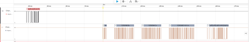
To test the feasibility of the CI-V communication, I programmed a simple response loop where the program (n1mm) send a frequency request and the program replies with the current frequency.
Bellow in the picture, channel 0 has the CI-V request and channel 1 replies with the debug messages and in the last frame the CI-V reply.
Signal Amplification
To make the counter work well all signals to be measured should be at TTL levels. I’m toying with 2 options:
1) Transistor + schimtt trigger
2) Comparator, like LM311
Simulating with ltspice, I got a pretty good result with the LM311, note the bias on the input.


The Transistor route is also worth exploring in case of difficulty with the LM.


I’ll put these in practice soon.